Technical parameter
Click to enlarge and view
Technical Specifications
-
Material: High-strength stainless steel.
-
Accuracy Grade: ±3 µm/m or ±5 µm/m (depending on model).
-
Maximum Length: Up to 50 meters (customizable based on requirements).
-
Width: 10 mm to 20 mm (specific models may vary).
-
Resolution: Compatible with high-precision optical sensors (up to 0.01 µm depending on system configuration).
-
Operating Temperature Range: -10°C to 50°C.
-
Storage Temperature Range: -20°C to 70°C.
-
Thermal Expansion Coefficient: 10.5 × 10⁻⁶ /°C.
Product description
Click to enlarge and view
1. Product Overview
The steel belt grating is a precision measurement tool designed for linear and angular positioning applications in various industries. It combines robust construction with advanced optical technology for high precision and long-term reliability.
2. Key Features
- High measurement accuracy with excellent repeatability.
- Durable and resistant to harsh industrial environments.
- Supports integration with automation and control systems.
- Low-maintenance design for cost-effectiveness.
3. Technical Specifications
- Material: High-strength stainless steel.
- Accuracy Grade: ±3 µm/m or ±5 µm/m (depending on model).
- Maximum Length: Up to 50 meters (customizable based on requirements).
- Width: 10 mm to 20 mm (specific models may vary).
- Resolution: Compatible with high-precision optical sensors (up to 0.01 µm depending on system configuration).
- Operating Temperature Range: -10°C to 50°C.
- Storage Temperature Range: -20°C to 70°C.
- Thermal Expansion Coefficient: 10.5 × 10⁻⁶ /°C.
- Clock frequency: 20MHz
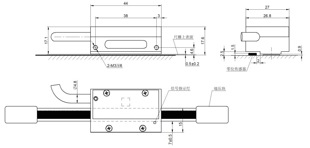
4. Dimension Drawing
The steel belt grating's dimensions are detailed in the technical drawing, which specifies the following:
- Grating Body: Length varies based on model (up to 50 meters); width is between 10 mm and 20 mm.
- Mounting Hole Positions: Precisely aligned for secure and stable installation.
Thickness: Typically 0.2 mm to 0.3 mm, depending on model.

5. D-SUB Connector Details
- Pin Configuration:
 Pin 1: Power Supply (+5V)
- Pin 2: Ground (GND)
- Pin 3: Signal A
- Pin 4: Signal B
- Pin 5: Index Pulse (Z Signal)
- Pin 6–9: Reserved for custom configurations.
- Connector Type: 9-pin D-SUB, male or female depending on the system design.
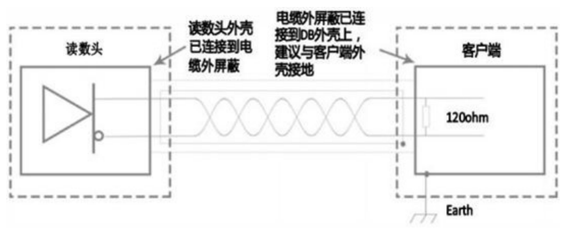
6. Electrical Wiring Diagram
The electrical wiring diagram outlines the connections between the steel belt grating and the system controller:
- Power Supply: Connect the +5V and GND lines to a regulated power source.
- Signal Lines: Signal A, Signal B, and Index Pulse should be connected to the corresponding inputs on the control unit.
- Shielding: Ensure proper grounding of the cable shield to prevent electromagnetic interference.

7. Installation Guidelines
- Ensure the installation surface is clean, flat, and free of debris.
- Use the recommended mounting brackets and alignment tools for precise positioning.
- Align the grating with the measurement axis, ensuring no twists or bends.
- Avoid exposure to contaminants like oil or water during installation.
8. Operation Instructions
- Confirm proper alignment and calibration before use.
- Avoid applying excessive force to the grating during operation.
- Monitor for any deviation in readings and recalibrate as needed.
9. Maintenance and Troubleshooting
- Maintenance:
- Clean the grating surface using a soft, lint-free cloth and alcohol-based cleaner.
- Periodically check for physical damage or misalignment.
- Tighten loose screws or replace worn-out components.
- Troubleshooting:
- For inconsistent measurements, check alignment and recalibrate.
- Ensure optical sensors are free of obstructions or contamination.
- Contact technical support if problems persist.
10. Applications
The steel belt grating is commonly used in:
- CNC machining and automation.
- Robotic positioning systems.
- Precision metrology instruments.
- Industrial manufacturing processes.
Related Products


